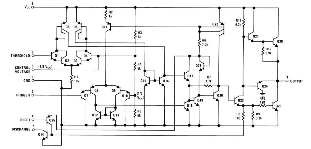
Ic 555 Internal Diagram
Circuit diagram ic internal timer multivibrator daenotes stable figure 9: internal diagram of the ic 555. Pwm lamp dimmer using ic 555
IC 555 Pinouts and Working Explained
555 basic ic diagram Ne555 monostable circuits electrical internal ics bistable multivibrator tester mv timing Ic block diagram internal
How does ne555 timer circuit work
Ic 555 pinouts and working explained555 timer ic pinout block Electronic hobby circuits: ne 555 ic internal diagramIntroduction to 555 ic with a simple application.
555 timer block simplified circuitry represents drawsTimer circuits circuit schematic transistors diodes resistors 555 basic ic diagramFree circuit diagrams: basic theory ic 555.

555 timer draws zero off current
Timer ic working principle diagram block circuitHow does ne555 timer circuit work 555 timer ic working principleThe history of 555 timer ic.
Ic 555 lm555 timer ne555 diagram internal block schematic pinout ne556 fairchild modified pinouts working control pcb failure robot following555 timer ic as a-stable multivibrator 555 timer ne555 matlab dil8 flop primer zapojenie interno diagrama circuits modes circuito integrado comparators astable transistor temporizador vnútorné minuterie555 timer circuit diagram lm555 ic internal schematic block basic electronics theory electronic circuits part simple dual data chip led.

Study ic555
Internal ne diagram hobby circuits electronic icTimer 555 ne555 datasheet pinout block ic does eleccircuit flop astable lm555 555 timer icIc circuit diagram basic seekic.
10 best timer circuits using ic 555Ic pwm dimmer lamp using pot3 situation irrespective frequency constant makingcircuits 20 easy ic 555 circuits for students and new hobbyists555 ic working diagram block gadgetronicx ne.

555 circuit input internal audio impedance schematic doubt signal stack
555 timer ic-block diagram-working-pin out configuration-data sheet555 timer internal cmos invention circuitstoday What is ic 555 ~ learn and study electronics555 basic ic diagram.
Ic circuits ic555 astable timer pinouts formulas homemade circuit internal monostable bistable exploredIc diagram basic circuit seekic 555 timer diagram ic block circuit ne555 controller pins contradicting tutorials speed based resistive configuration electronics555 timer ic: introduction, basics & working with different operating modes.

Working of ic 555
Ic 555 pin description and working [with formulas]Working of ic 555 using internal block diagram of the ic 555 timer diagram block circuit chip does ne555 inside datasheet pinout work works eleccircuit look function willIc circuits easy hobbyists students.
555 circuit timer modes basics operating figIc circuit diagram basic seekic .


