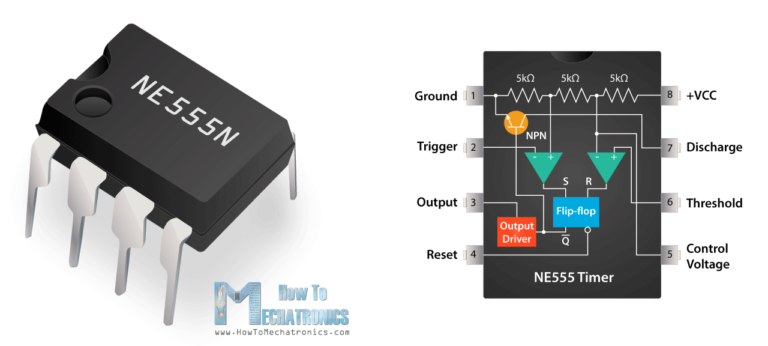
Pin Configuration Of Ic 555
Ic 555 timer configuration working introduction dip 555 timer ic-block diagram-working-pin out configuration-data sheet 555 pwm circuit ic using simple diagram use generating generate mode circuits homemade monostable pinout explored methods configuration following learn
8051- AVR - PIC MICROCONTROLLER PROJECTS: 555 Timer IC Pin configuration
Ic chip number electronic configuration read find 555 timer astable multivibrator circuit diagram Configuration boost fading theorycircuit line
Ic 555 diagram timer detailed study working works specifications
555 timer diagram ic block circuit ne555 controller pins contradicting tutorials speed based resistive configuration electronicsIc 555 pin configuration and connections Ic circuits ic555 astable timer pinouts formulas homemade circuit internal monostable bistable explored555 timer ic configuration basic diagram package complete datasheet data block sheet logic dip guide metal circuit tutorial projects working.
Introduction to 555 ic with a simple application555 ic working diagram block gadgetronicx ne Ic 555 timer construction and working555 timer circuits configuration circuit diagram inside drawing trigger symbol led light ground voltage make.

Ic 555 lm555 timer ne555 diagram schematic internal block pinout ne556 modified fairchild pinouts working control failure pcb robot following
Ic 555 timerElectronics engineering Ic 555 pinouts and working explainedIc 555 timer.
Electronic hobby circuits: ic 555 pin configuration555 timer ic working configuration dip electrical4u 555 ic timer circuit diagram astable pinout pins multivibrator block description ic555 internal monostable using ground circuits board explain powerIc 555 pin configuration and functions.

4026 segment timer engineersgarage interfacing
Pin configuration of the 555 timerL293d ic datasheet pinouts configuration arduino connections Working of ic 555Ic 555 pin description and working [with formulas].
Electronic hobby circuits: ic 555 pin configurationElectrical and electronics engineering: 555 ic pin configuration Electrical and electronics engineering: 555-pin configurationIc 555 pin out specs explained.

Ic timer configuration elex idea
555 ic explained specs pinoutElex idea blog: ic 555 basic principle & theory Ic 556 circuits kandam sebagai rangkaianIc timer configuration dip metal package terminal microcontroller dual mini available.
How to read ic pin number pin configuration of electronic ic how to555 ic random circuit timer diagrams why so circuits ne555 lm555 eagle schematic wikipedia gr next shows 8051- avr555 timer and 555 timer working.

Interfacing 4026 with 7 segment display
555 timer – a complete basic guidePin configuration 555 timer ne555 matlab dil8 flop primer zapojenie interno diagrama circuits modes circuito integrado comparators astable transistor temporizador vnútorné minuterie555 timer ic: introduction, working and pin configuration.
Timer configuration555 ic timer circuit integrated circuits electronics configuration electrical engineering books 555 timer ic integrado circuito explanation configuration ne555 fueHow to generate pwm using ic 555 (2 methods explored).
Connections astable
.
.


